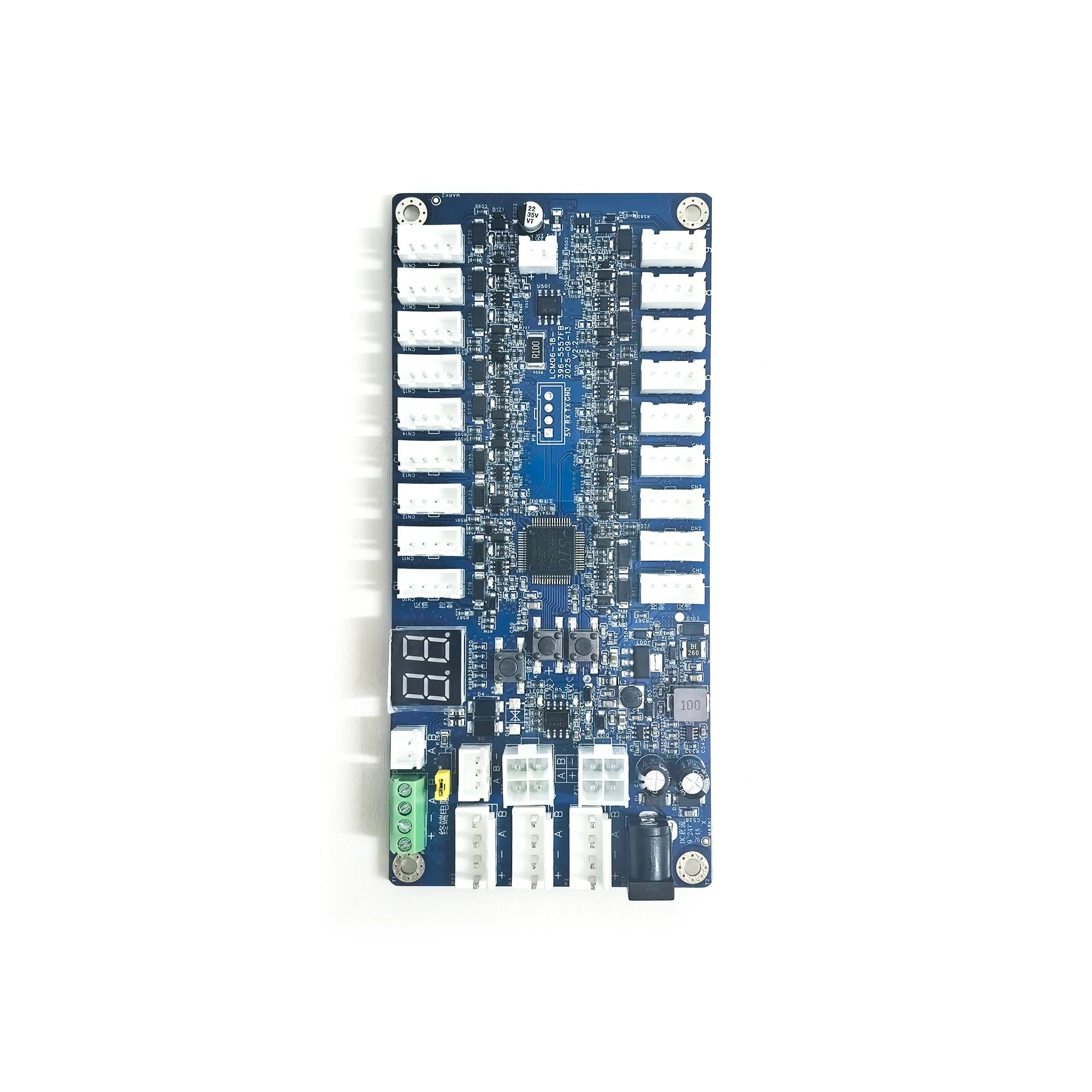
Overview: What Is a 24-Channel Lock Control Board
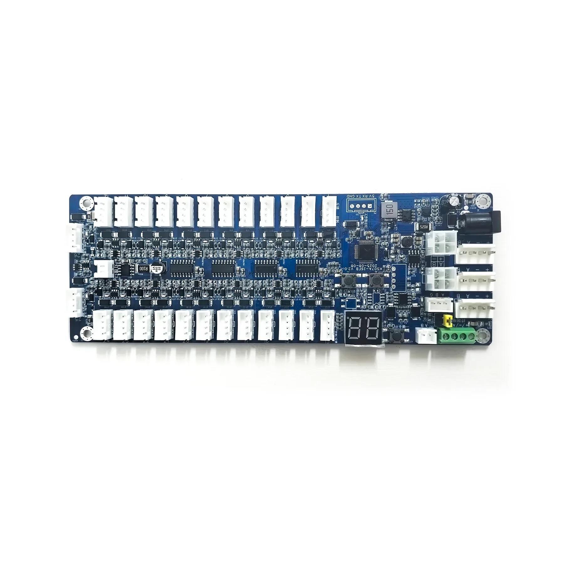
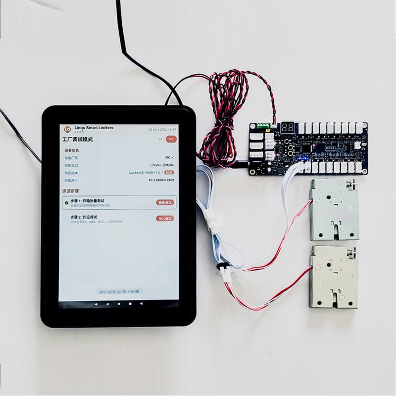
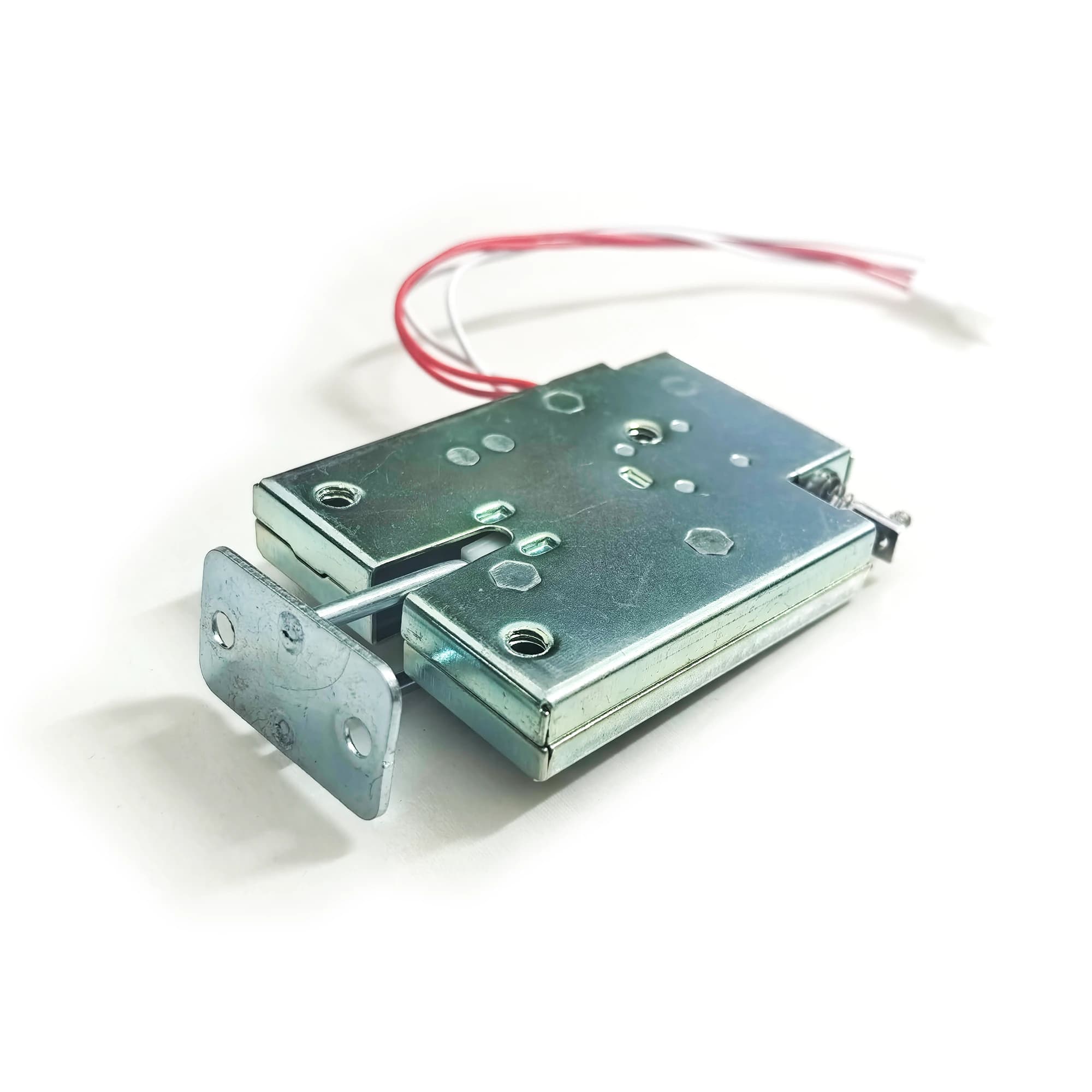
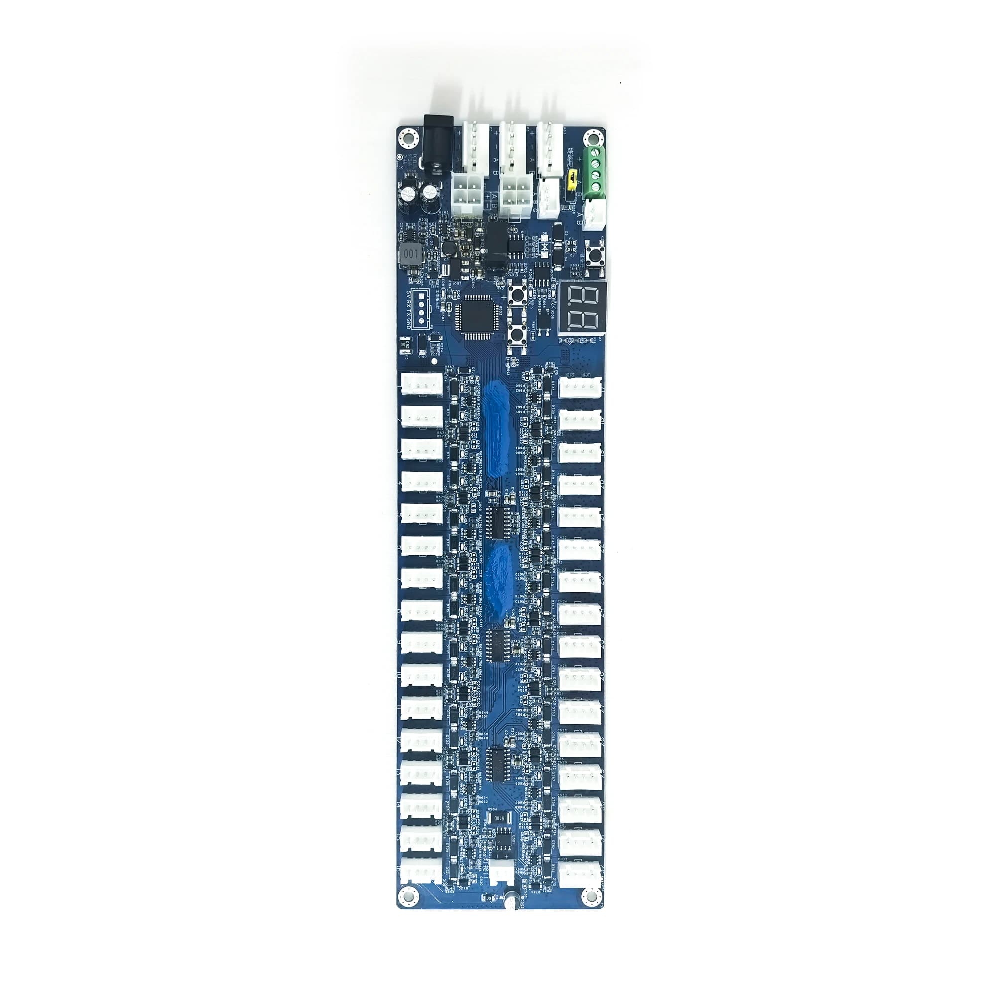
The LinQu 24-channel lock control board (model LCM06-24-396-5557FB) is the electronic lock controller that sits in the control compartment of a smart locker. One board independently controls 24 locker doors, detects the lock state and door sensor state of every channel, and reports back to the main controller or Android touchscreen over RS485. It is designed and manufactured in-house by LinQu (headquarters in Zhengzhou, factory in Luoyang). You can buy it on its own or as a set with a touchscreen and electronic locks, for smart locker OEM / ODM and system integration projects.
The 24-channel board sits between the 18-channel lock control board and the 32-channel lock control board. For a locker whose door count falls between the two, a single 24-channel board covers it, with fewer idle channels and one board less to wire.
How It Works in a Smart Locker
The typical chain is: your platform or app → Android touchscreen / main controller → RS485 → lock control board → each electronic lock.
| Stage | What it does |
|---|
| Upper system | A cloud platform, app or local management system sends the open-door command |
| Main controller / Android screen | Sends the unlock command over RS485 (9600 baud) to the board with the target address |
| Lock control board | Drives the matching channel to unlock; detects lock state and door sensor state in real time and reports to the main controller; can raise an alarm on abnormal door status |
| Status indication | One LED per channel: on when the door is open, off when it is closed; the digital display shows the board address and fault codes |
| Fault handling | If a lock channel is short-circuited, the display shows "Er + channel number" (e.g. Er 03), that channel is blocked from unlocking, and the fault is reported to the upper system |
Multiple lock control boards are cascaded over RS485 and told apart by board address (1–199), so one main controller can manage several master and slave cabinets.

18, 24 or 32 Channels: Which to Choose
| Model | Channels | Board size | Best for |
|---|
| LCM06-18-396-5557FB | 18 | 140mm × 65mm | Lockers with fewer doors |
| LCM06-24-396-5557FB | 24 | 179mm × 65mm | Lockers with a door count between the 18- and 32-channel boards |
| LCM06-32-396-5557FB | 32 | 243mm × 65mm | High-density lockers with many doors |
All three share the same working voltage, lock voltage, communication, protection features and setup method; they differ only in channel count and board length. Choose the board by the number of doors per cabinet, and first check the board length your control compartment can fit.
24-Channel Lock Control Board Specifications
| Item | Specification |
|---|
| Model | LCM06-24-396-5557FB |
| Lock channels | 24, independently controlled |
| Communication interface | RS485, multi-board cascading |
| Baud rate | 9600 |
| Working voltage | 9V – 24V DC |
| Lock voltage | 9V – 24V DC |
| Unlock current | < 3A |
| Standby current | ≤ 35mA (12V) |
| Working temperature | -40°C – 85°C |
| Working humidity | 0% – 90% RH, non-condensing |
| Board size | 179mm × 65mm |
| Mounting hole diameter | 3mm |
| Board address | 1 – 199, set on site with buttons |
| Door logic | Switchable normally open / normally closed |
| Status indication | LED per channel + digital display |
| Protection | Reverse polarity, RS485 miswiring, lock short circuit, lightning surge, ESD (level 3); waterproof and dustproof design |
| Power supply | Switching power supply |
Installation and On-Site Setup
The board has its own digital display and buttons, so address, door logic and test unlocking can all be done on site without connecting a computer. The video in the product gallery shows how to switch the door logic.
| Task | How |
|---|
| Set the board address | Hold "+" or "-" for 3 seconds; when the display flashes, adjust the address; it saves automatically 3 seconds after you release |
| One-key unlock (installation test) | Hold the "one-key unlock" button for 3 seconds to start cycling through all locks; hold 3 seconds again to stop |
| Door logic (NO / NC) | After power-on, double-click the unlock button, choose the mode and press "+" to save |
| Lock short-circuit alarm | The display shows Er + channel number; that channel is blocked from unlocking and the fault is reported to the upper system |
How many boards can be cascaded depends on the power configuration. Reference values:
| Power configuration | Power supply | Total power | Recommended boards in cascade |
|---|
| Single side, single supply | 12V / 5A | 15W | ≤ 19 |
| Single side, single supply | 15V / 5A | 28W | ≤ 35 |
| Single side, single supply | 24V / 5A | 48W | ≤ 62 |
| Double side, single supply | 24V / 10A | 101W | ≤ 130 |
| Single side, dual supply | 24V / 10A | 103W | ≤ 132 |
Note: these figures come from laboratory test conditions and are for reference only.
Purchasing Options and System Integration
| Option | Details |
|---|
| Lock control board only | You already have cabinets and a main controller and only need to add or replace boards; you can order a sample to test first |
| Component set | Buy together with the Android touchscreen and electronic locks to reduce compatibility debugging |
| Complete locker OEM / ODM | Cabinet, screen, boards, locks and software customized as a whole, shipped under your brand for your use case |
| Integration with your platform | Complete-locker projects come with an open API / SDK, interface documentation and technical support; this is an open-interface approach, not a ready-made third-party plugin |
When requesting a quote, please tell us: door count per cabinet, lock voltage (12V or 24V), power supply plan, main controller type, and whether you need to connect your own platform. For which parameters to check on lock control boards, touchscreens and electromagnetic locks, see the Smart Locker Control Components Selection Guide.
Ordering and Warranty
| Item | Details |
|---|
| MOQ | 1 piece |
| Samples | 7–14 days; buyer covers sample cost and shipping |
| Bulk lead time | About 20 days from configuration confirmation; design changes require a new estimate |
| Payment | T/T; Alibaba Trade Assurance supported |
| Warranty | 1 year, free replacement for hardware issues |
| Quotation | Reply within 24 hours |
For the full process from sample to bulk order, see How to Order Smart Lockers from a Manufacturer: MOQ, Samples and Lead Time. Send us your door count and wiring requirements by email or WhatsApp and we will reply within 24 hours.